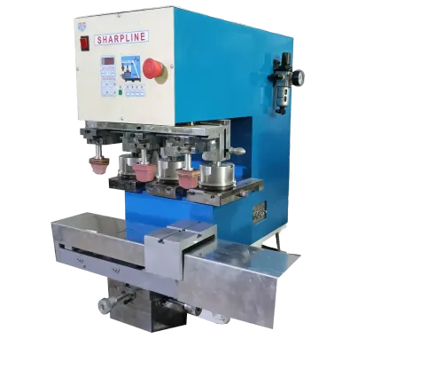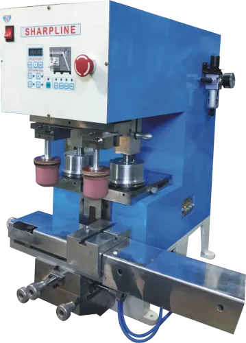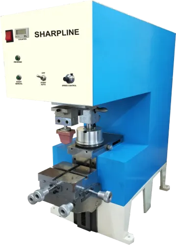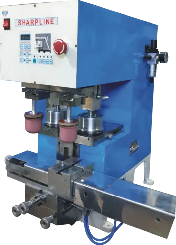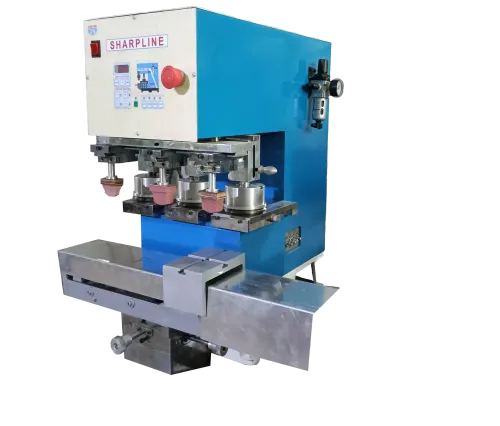
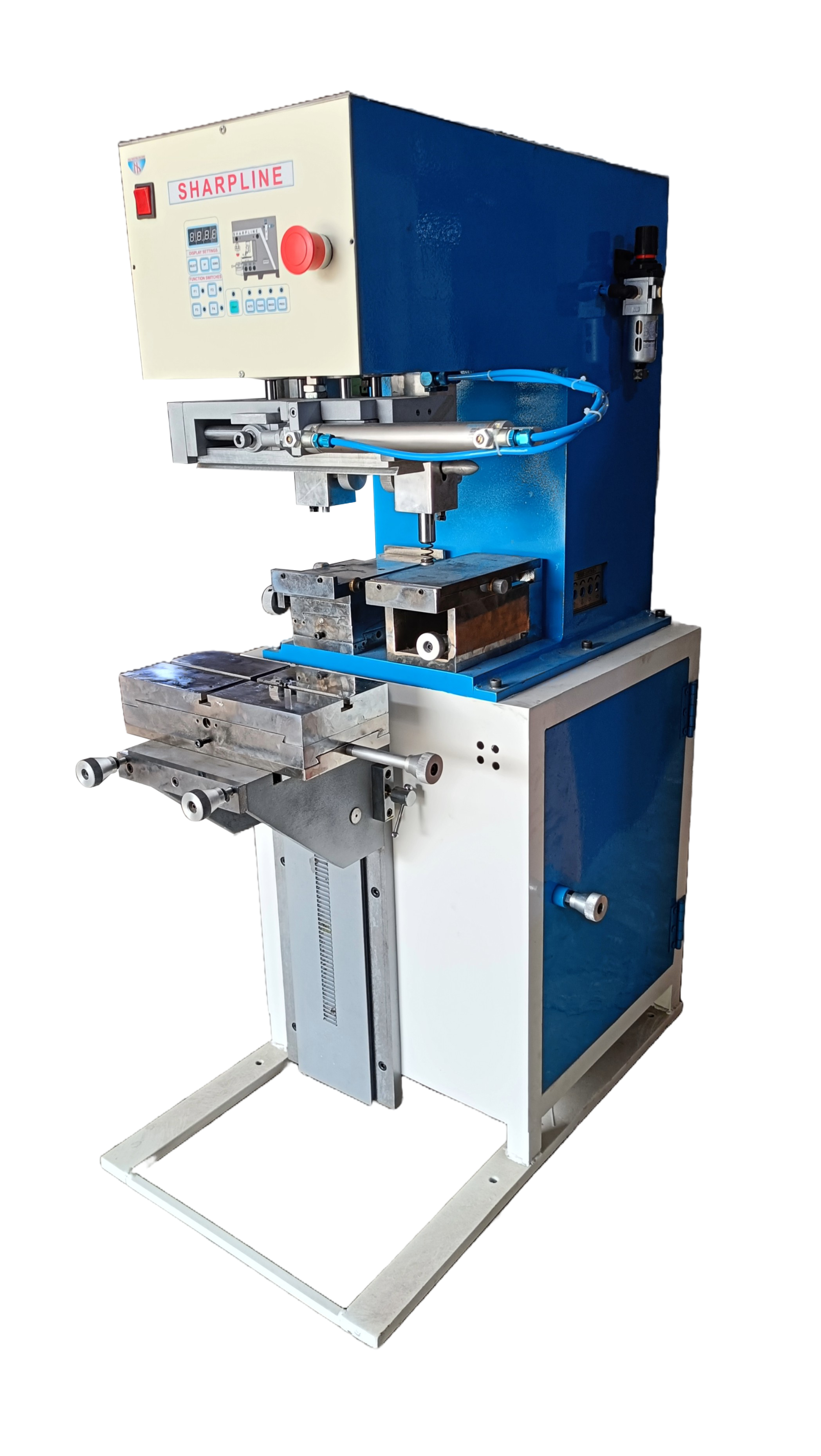
A pneumatic pad printer is not matched to a factory by its advertised stroke rate or maximum pad diameter alone. You will be able to turn your part, artwork, air supply, output target, and quality requirements into a practical machine specification—and test whether the promised process capability is real.
Key takeaways
- Test the part, artwork and print finish before selecting machine force or stroke.
- Convert hourly output into a verified cycle rate using a production-part trial.
- Check compressor pressure, air volume, filtration and reservoir capacity before buying.
- Choose pneumatic, motorised or manual motion based on workload and repeatability.
Start with the Part, Artwork, and Printing Process
Start with the part, because force and stroke cannot rescue a poor process fit. A pneumatic pad printing machine supplier must review the component’s material, shape, flexibility, available print faces, image dimensions, colour count, and required finish before recommending equipment.
| Production detail | Why it determines suitability | What failure looks like |
|---|---|---|
| Part geometry and fixture | The machine must position every datum at a repeatable height and angle; the pad must reach the surface without collision. | Parts shift, rotate, flex, or print at inconsistent positions. |
| Artwork and pad geometry | The largest image must fit within the pad’s usable compression area, with enough contour to transfer ink without excessive deflection. | Fine lines stretch, corners lose definition, or the image distorts. |
| Substrate and ink system | Ink adhesion, drying or curing, and abrasion resistance depend on the material and selected ink system. | The image wipes off, fails tape or rub testing, or never reaches the required finish. |
| Colour and print locations | Multi-colour work requires accurate indexing, station repeatability, drying time, and mechanical or programmable registration adjustment. | Separate colours drift even though each cliché is correct. |
| Production sequence | Size the machine against pad pickup, transfer, return, loading, indexing, inspection, and dwell—not an unloaded cylinder stroke. | The advertised rate misses the target once an operator handles parts. |
Confirm operator involvement too: manual loading, automatic handling, inspection, and changeover time alter the practical machine choice. Approve the process only after a trial on production parts verifies position, adhesion, registration, and cosmetic quality over a representative run.
Convert the Production Target into a Tested Cycle Rate
A target of 12,000 good parts per shift requires more than dividing 12,000 by eight hours. Subtract breaks, planned maintenance, changeovers, cleaning, and other scheduled downtime, then allow for expected rejects. If 480 minutes contains 45 minutes of breaks, 30 minutes of changeover, and 15% planned production loss, net time is 344 minutes.
With 2% rejects, the machine must produce 12,245 parts, or 35.6 parts per minute. One part per cycle means a required cycle time of 1.69 seconds.
Use this calculation:
- Good parts required ÷ (1 − planned scrap rate) = parts to print
- Parts to print ÷ net production minutes = required parts per minute
- 60 seconds ÷ required parts per minute = maximum cycle time
- Required parts per minute ÷ parts printed per cycle = required machine cycles per minute
The cycle must include pad pickup, ink transfer, pad return, part loading, unloading, indexing, and any ink-transfer dwell or drying time. A cylinder’s unloaded stroke rate does not represent sustained output; a pneumatic machine for production can miss its target when handling and operator tasks are added.
Ask for a timed trial using your production part, fixture, artwork, ink system, operating pressure, and normal loading method. Record good parts per hour, rejects, stoppages, changeover time, and operator actions. Compare that sustained figure with your calculated requirement, not the supplier’s headline strokes-per-minute figure.
If the margin is small, specify extra capacity or reduce the bottleneck before approval.
Specify the Air System Before Choosing the Machine
A stated 6-bar requirement proves little unless the machine still receives that pressure during its fastest cycle. Ask for inlet pressure at peak demand, air consumption per cycle and per minute, peak flow, test pressure, and the number of pneumatic axes operating together.
Compare those figures with the compressor’s free-air delivery, not the receiver’s nominal tank volume.
- Match the machine to the largest image, part height, pad compression area, ink system, and required cycle time. Excessive pad deflection distorts fine details and registration.
- Specify clean, dry air, correctly sized hoses, filters, regulator, moisture separator or dryer, and quick couplings. Undersized fittings create pressure drop; water or oil contamination changes ink transfer.
- Confirm the site electrical supply, control voltage, connection standard, exhaust arrangement, noise exposure, receiver capacity, and local spare-parts and service support.
- Require guarding, interlocked access, emergency stopping, unexpected-restart protection, and a dump valve that releases stored air. Assess the complete installation under ISO 12100 and ISO 4414, including automatic part handling.
Use the force estimate pressure × piston area, minus seal friction and other losses, to check suitability. A larger cylinder raises force but also consumes more air and can slow motion unless the valve, regulator, and supply are upgraded.
| Check | Nominal claim | Production-ready match |
|---|---|---|
| Air supply | “6 bar available” | Pressure maintained at the machine during peak flow |
| Capacity | Receiver volume | Compressor free-air delivery exceeds demand |
| Safety | Guard on the machine | Guarding, interlocks, air dump, restart control, and downstream handling assessed |
Choose Pneumatic, Motorised, or Manual Motion for the Workload
Pneumatic motion suits a workload that repeats the same stroke, transfer, and return cycle throughout the shift. Valves and pressure controls let you regulate speed and force without the cost or programming burden of a servo axis. Changeovers stay practical when you can adjust pad height, stroke, dwell, and fixture position mechanically.
| Motion | Strength | Choose it when |
|---|---|---|
| Manual | Lowest complexity | Volumes are low and an operator loads, prints, and unloads each part |
| Pneumatic | Fast, robust, adjustable | The stroke repeats, output is steady, and operator loading remains part of the cycle |
| Motorised or servo | Programmable positioning | You need coordinated axes, stored motion profiles, rapid format changes, or tight registration |
Do not select pneumatic equipment from cylinder speed or maximum pad diameter alone. Match the machine to the largest image, pad compression area, part geometry, ink system, substrate, colour count, and tested cycle containing loading, indexing, dwell, transfer, and unloading. Excessive pad deflection can blur fine artwork even when the machine reaches its advertised rate.
Pneumatic pad printing machines in India also need a site-specific check: confirm electrical supply, control voltage, air connection, filtration, spare parts, and service response. Choose pneumatic when:
- The fixture holds the datum without shift, rotation, or flex.
- One operator can load and inspect parts without creating a bottleneck.
- Adjustments, rather than programmed motion, handle the expected changeovers.
Choose motorised or hybrid motion when registration depends on coordinated multi-axis movement or frequent recipe changes.
Use a Production-Part Trial to Compare Suppliers
Do not approve a pneumatic machine from a catalogue figure. Require a production-part trial using your actual substrate, artwork, ink system, fixture, and operating sequence. A pad printing machine supplier for pneumatic machine applications must prove process capability, not only cylinder force, stroke, or nominal print area.
Ask the supplier to provide:
- A fixture built around your production datum scheme, with evidence that parts do not shift, rotate, flex, or sit at different heights.
- Samples from a representative run, checked for image position, fine-feature definition, adhesion, abrasion resistance, smearing, pinholes, and other cosmetic defects.
- The largest required image, pad geometry, compression setting, cliché size, ink, thinner, drying time, and cure conditions used in the trial.
- The measured cycle time for loading, indexing, pad pickup, transfer, return, unloading, drying or dwell, and inspection—not an unloaded cylinder stroke.
- Air consumption per cycle, peak demand, test pressure, simultaneous pneumatic axes, and the pressure measured at the machine inlet.
- For multi-colour work, registration results across stations and the mechanical or programmable adjustments used to correct drift.
| Trial evidence | Approve when | Reject when |
|---|---|---|
| Fixture repeatability | Datum location stays consistent | Parts move or vary in height |
| Print quality | Position, adhesion, and cosmetics pass | Any required feature fails |
| Output | Sustained rate meets the target | Headline speed excludes handling |
| Utilities | Compressor and line maintain pressure | Pressure drops during cycling |
SHARPLINE ENGINEERS can be asked to document these results against your acceptance limits, rather than presenting machine specifications as proof of production performance.
Related product
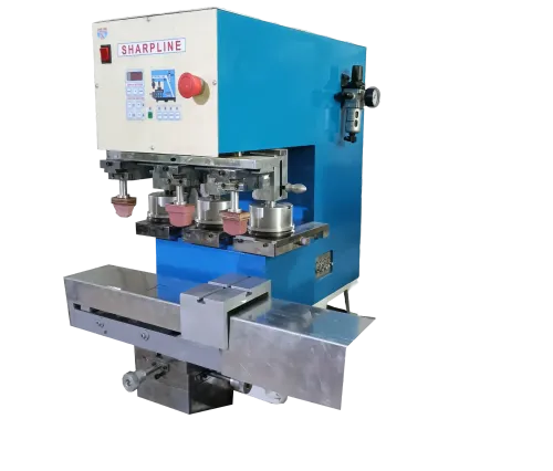
 | PNEUMATIC PAD PRINTING MACHINE PNEUMATIC PAD PRINTING MACHINE Single color, Non-Magnetic Tungsten carbide steel ring & compact sealed Ink cup Pad Printing machine Max. View product → |
Frequently asked questions
What should a supplier review before recommending a pneumatic pad printing machine?
Review the component material, shape, flexibility, available print faces, image size, colour count and required finish.
How do you convert a production target into a machine cycle rate?
Calculate the required cycles per hour, then verify the rate with a production-part trial that includes loading, printing, curing and unloading.
What air-system details must you specify for a pneumatic pad printing machine?
Confirm operating pressure, air consumption, compressor capacity, filtration, regulation and reservoir size against the machine’s tested demand.
When is pneumatic motion a better choice than motorised or manual motion?
Choose pneumatic motion for repeatable production cycles and straightforward force control; compare motorised motion for programmable sequences and manual motion for low-volume work.
Keywords